 Still need to add figures 2-4.
What's New
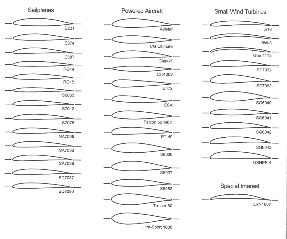
Volume 3 is Coming! Since our last Newsletter of Sept. 1996, our overdue Volume 3 has grown to an eye-popping 400+ pages of airfoil data, and it should be available in Jan-Feb 1998. While our plans were to publish Volume 3 as early as January 1997, the writing of the book stretched into the Spring 1997 and then into the next Test Series (the 4th). As a result, it only then made sense to delay the book and combine the 3rd and 4th Test Series into a large volume. It will be worth the wait: Volume 3 includes tests on over 37 airfoils shown below.
Among these are 3 new airfoils for sailplanes (SA7035, SA7036, SA7038), 3 new airfoils for powered aircraft (S8036, S8037, S8052), and 4 new airfoils for small wind turbines (SG6040, SG6041, SG6042, SG6043). In response to modelers' requests, several airfoils were also tested with small flap deflections. In addition to the standard performance data for each airfoil (drag poloar and lift curves), Volume 3 also includes extensive pitching moment data acquired over a broad range of Reynolds numbers and angles of attack, as well as a chapter specifically devoted to the effects of boundary-layer trips on low Reynolds number airfoils.
Next Test Phase (Test Series 5) It's that time of the year again, which means by the time you receive this newsletter the LSATs team should already be in the tunnel (or almost in the tunnel) acquiring data for Volume 4. As usual, we've made some pretty big plans for this test phase. First, we've made several improvements to our testing apparatus which should not only increase the amount of data we can acquire, but also improve data quality. Among these changes are a new wake traverse for drag acquisition, the addition of two new wake pressure transducers allowing us to take twice as much data in the same amount of time, and the implementation of low-friction bearings in the lift balance to allow data acquisition below Re = 60,000.
Not only do we have major improvements to the setup, but several new airfoils are slated to be tested as well. Currently being designed are thinned versions of the SD7037, a new sport-plane airfoil (Clark-Y derivative), a new symmetric airfoil for aerobatic aircraft, several flying-wing airfoils, and also two new small wind turbine airfoils.
Transition from Lyon to Carroll In December, Chris Lyon is leaving as the LSAT coordinator to pursue other areas within the research group (we are not sure yet what that will be, but it will surely leave time open for him to bring the new coordinator up to speed). Taking over for him is Chris Carroll, a first year graduate student in Aero/Astro Engineering. In addition to his interest in aircraft design, Chris is also an accomplished musician. Before attending UIUC he spent 8 years as a professional musician releasing several recordings on a major label. During this same period he worked as a session musician in New York City were he recorded numerous TV and radio commercials, and wrote, recorded, and produced several movie sound tracks. While attending UIUC as an undergraduate he released two independent recordings and worked as a session musician in Chicago. Other interests include, muscle cars, guitar collector, avid history buff, surfing, skateboarding, and illustration. More about Chris Carroll is included in our Points of Contact section.
SA Airfoils A survey conducted by Selig and Ninham at the 1996 AMA/LSF Nationals showed that the most popular airfoil among those competing in the Unlimited Thermal Soaring Competition by far was the SD7037 (see Camberline Newsletter No. 4 at the LSATs web site for more details on the survey). The popularity of the SD7037 has led us to develop a new family of SD7037-based airfoils that differ in their thicknesses (9.2%, 7.7% and 6.2%) and useful lift ranges. Such a family of airfoils would enable a sailplane designer to migrate from one airfoil to another when designing sailplanes with different wing loadings, as well as provide aerodynamically-similar airfoils for varying airfoils along the wing span from root to tip.
As a first step in this process, three new airfoils have been designed - the 9.2% thick Selig/Ashok Gopalarathnam SA7035, SA7036 and the SA7038. These three airfoils have been designed using the inverse airfoil design code PROFOIL (see PROFOIL-WWW at http://www.profoil.org) to have different lift ranges, while sharing characteristics common to the SD7037 (e.g., the aerodynamic characteristics and geometric thickness). In particular, the SA7035 and SA7036 are lower-lift versions of the SD7037 and the SA7038 is a higher-lift version. Shown in Figs. 1 and 2 are the airfoils (plotted in expanded view) and XFOIL Version 6.2 predictions for the three new airfoils, compared with that of the SD7037. The different lift ranges for the four airfoils are clearly seen in this comparison. Experimental results for the new airfoils are included in Summary of Low-Speed Airfoil Data, Vol. 3. Coordinates and a more length discussion of the airfoils are available on the www are the UIUC LSATs web site. That such a series of airfoils has been needed for quite some time is evident from the fact that already several kits that we know of have been designed using the new airfoils.
The thinner versions of this series are currently being designed. We plan to test these thinner airfoils in Test Series 5. When completed, the final family of airfoils will consist of 12 airfoils, one of which will be the SD7037. Designers will then be able to choose the best airfoil combination (from root to tip) to fine tune the performance of their new designs. Also being planned for Test Series 5 are tests of the SA7035 with trailing-edge flap deflections and tests of a new model of the SD7080 to provide a good comparison of the performance with that of the SA7035.
Report on Gurney Flaps Following the tests performed with Gurney flaps that were documented in the second volume of Summary of Low Speed Airfoil Data, some modelers have experimented with this kind of flap. R.J. Edwards from England reports that he has been experimenting with Gurney flaps on his Algebra R/C sailplane that has a 98 in span, 870 sq. in wing area, 9 oz/ft2 wing loading and that uses a rudder elevator combination for control on a V-tail arrangement.
From the discussion of Gurney flaps in Volume 2, R.J. Edwards decided to use a wing made up of a thicker airfoil, the SD7062, compared to the SD7037, which is used on the production wings of the Algebra. The first set of experiments consisted of gluing a 1%c Gurney flap, made from 0.032 in (0.8 mm) birch plywood, onto the right wing only. The flap length was tapered according to the wing taper. After carefully trimming the sailplane to fly ``dead straight'' without the Gurney flap, test flights with the Gurney flap revealed that the sailplane turned noticeably to the left. A 3/16 in rudder deflection was required to bring the sailplane back to straight flight. R.J. Edwards also performed similar tests with a 13 ft span soarer equipped with a wing using the SD7032 airfoil. The results were not quite as positive as the tests with the Algebra but the 13 ft soarer definitely entered a turn with the Gurney flap on only one wing. A friend of R.J. Edwards, Peter Allen, also conducted the same tests with his 12-ft soarer using the SD7032 airfoil and obtained similar results. R.J. Edwards also experimented with 0.5%c Gurney flaps and interestingly enough, he concluded that this flap length provided the same results as a 1%c flap. Additional tests were also performed to estimate the model's average airspeed with and without Gurney flaps. Repeated measurements over a given course indicated that their sailplanes equipped with Gurney flaps had a 23% increase in average speed (20.3 mph with flaps vs 16.5 mph without flaps) when using a 1%c Gurney flaps. As pointed out by R.J. Edwards, such results must be interpreted with care, however, owing to the uncertainty involved in those tests.
Based on their tests, R.J. Edwards and Allen entered a thermal soaring contest in England with sailplanes equipped with Gurney flaps. On the day of the competition, atmospheric conditions favored large lightly loaded models, which R.J. Edwards and Allen had. The competition consisted of both an individual and team (of two pilots) contest in which R.J. Edwards and Allen won both (Allen won the individual event). As pointed out by R.J. Edwards, how much the Gurney flaps contributed to their success is hard to say but he is convinced that his model performs better than it did without the Gurney flaps.
Hopefully, the experience of R.J. Edwards and Allen with Gurney flaps will promote additional tests on this kind of flap and on other devices such as trips. We thank R.J. Edwards for sharing his experience with us and welcome other modelers to do the same with their own testing.
Points of Contact. You can write, e-mail (preferred), fax or call any of us. Use the fax number and address later listed for Michael Selig. To help you decide who to write to, you might want to consider our profiles:
In Other News
``High-Flyers'' Prof. Michael Selig has recently finished the design of a new airfoil to be used on the AeroVironment solar-electric powered Centurion. The aircraft is funded under the NASA Environmental Research and Aircraft Sensor Technology (ERAST) program. The founder and CEO of AeroVironment, Inc. is Dr. Paul MacCready known for his work on the Gossamer Condor and Albatross (winners of the first and second Kremer Prizes), the Solar Challenger, and GM Sunraycer and Impact. The 220-ft span 8-ft chord flying-wing Centurion is designed to reach 100,000 ft using solar power to drive 10-14 propellers positioned along the wing. Tests on the new airfoil were conducted in the UIUC Subsonic Aerodynamics Lab through the diligent efforts of graduate students Chris Lyon, Ashok Gopalarathnam, Chris Fisichella and Philippe Giguère. The tests confirmed the predicted performance of the new airfoil and the feasibility of reaching 100,000 ft under solar power. A quarter-scale version of the Centurion using a modified Liebeck (PhD, UIUC 1968) airfoil was recently flown and subsequently discussed in Aviation Week and Space Technology (March 17, 1997, p. 36). Mention of Prof Selig's involvement is given there.
Prior to this more recent effort, Chris Lyon and Prof. Michael Selig conducted a series of tests in April 1996 to improve the performance of the Liebeck airfoil used on the AeroVironment Pathfinder - a predecessor to the Centurion (cover story Popular Science, April 1994). The Pathfinder reached an altitude of 50,500 ft on Sept 12, 1995. Interest in flying higher prompted the UIUC investigation to document the airfoil performance and suggest improvements to the design. Using boundary-layer trips to improve the low Reynolds number performance, the drag was reduced markedly over a large angle of attack range.
Photos of the Pathfinder can be found at the site: http://www.dfrc.nasa.gov/Gallery/Photo/Pathfinder/index.html
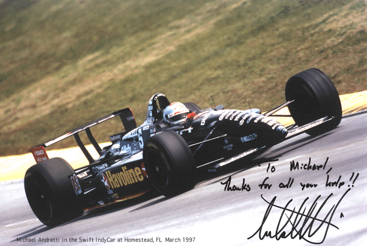
`` The Need for Speed'' ``I feel the need for speed'' were actor Paul Newman's words before the 1st PPG Indy Car CART race of the 1997 season in Homestead Florida. Those words rang true at the end of the race when Michael Andretti finished 1st in a field of nearly 30 drivers (cover story RACER, May 1997, cover story Racecar Engineering, Vol 7, No 3, 1997, and AutoWeek, March 10, 1997, Road and Track, April 1997). Paul Newman is co-owner of Newman-Haas Racing with drivers Michael Andretti and Christian Fittipaldi. The good showing of Fittipaldi during the race was stalled when he was black flagged for an oil leak. The Andretti victory marks the first time in 14 years that a American designed and built chassis has won an Indy-car race.
Prof. Michael Selig and Ashok Gopalarathnam played a key role in the victory. For nearly 2 years, through the support of Ford Motor Company, they have been developing a design methodology for high down-force Indy-car wings in support of Newman-Haas Racing (NHR). More recently, William J. Jasinski (ME, graduate student) and Dr. Antonio Filippone (Postdoc) have been involved with the effort. The wings used in the Homestead race were designed by Prof. Michael Selig using the software developed for Ford in support of their motorsports activities. Those same wings were used at the Michigan US 500, and the California 500, where Andretti quickly moved through the grid to lead the race, only to drop out because of mechanical problems. Selig and his group were special guests of NHR at the PPG CART race at the Gateway International Raceway (St. Louis). Also, Selig attended a closed test at Fontana (location of the California 500) and got a 100-mph tour of the new 2.5-mile race track with Andretti behind the wheel of a Lincoln Town Car!
Ashok Gopalarathnam and Prof. Michael Selig presented a paper on the method entitled ``Design of High-Lift Airfoils for Low Aspect Ratio Wings with Endplates'' (AIAA Paper 97-2232) at this past summer's AIAA Applied Aerodynamics Conference in Atlanta.
A picture of the Andretti car can be found at https://m-selig.ae.illinois.edu/gifs/andretti.gif
AIAA Design/Build/Fly Competition A group of students from the UIUC, including 3 LSATs team members [Andy Broeren (team leader), Chris Lyon (pilot), and Ashok Gopalarathnam], recently competed in the first annual AIAA (American Institute of Aeronautics and Astronautics) R/C Electric Design/Build/Fly Competition. The objective was to design, build, and then fly an electric aircraft optimized for maximum range fueled by 2.5 lb of NiCd batteries while carrying a 7.5-lb payload. The design team, which was generously sponsored by Hobbico and others, was comprised of students with various backgrounds (freshman - graduate) both with and without modeling experience. After 12 months of hard work and the destruction of one prototype aircraft, the UIUC team won the competition in overwhelming fashion. The final design had a 12-ft wingspan, used the Clark-Y (favored for it's thickness), weighed 18.5 lb, and was powered by a MaxCim 15-13Y brushless motor. For more information regarding the design of this aircraft, feel free to contact either Chris Lyon or Ashok Gopalarathnam at (217) 244-0492 or Andy Broeren at (217) 244-3128.
Unsteady Aerodynamics at Low Reynolds Numbers Stall characteristics are often considered when selecting an airfoil for a particular application. For example, it is almost always desirable for an airfoil to have a ``gentle'' stall, or gradual loss of lift beyond Cl,max. It has been known for many years that stall is generally accompanied by unsteady flow over the airfoil. Depending on the intensity of this unsteady flow, there may occur large fluctuations in lift, drag and pitching moment. Usually these effects are small and ``averaged out'' during wind-tunnel testing.
Recently, some research has been conducted into the level, or intensity, of flow unsteadiness during stall. This has been accomplished by measuring the lift force changes as a function of time, which requires some modifications to the existing test apparatus. The root-mean-square (rms) value of the lift coefficient is used to determine the intensity of lift fluctuations. The rms lift coefficient (Cl,rms) represents the average value of the fluctuating portion of the lift.
Consider Fig. 3, which shows the lift curve for the S8036 (designed originally for the Top Flight P-47 Thunderbolt) as well as the Cl,rms associated with each lift coefficient. Notice how the Cl,rms increases slightly as the airfoil reaches maximum lift (about 19 deg). This elevated Cl,rms level remains until the lift is regained as the angle of attack is decreased to about 15 deg. Compare this to Fig. 4, for the E374, which shows a large increase in Cl,rms at Cl,max. Hence the stall of the E374 is much more unsteady than for the S8036 and as a result the lift fluctuations (and presumably the drag and pitching moment) are much more severe.
While these results are interesting, if not surprising, it is not clear if such behavior is observed on aircraft that use the E374 airfoil. The stalling process of a wing can be much different from that of a two-dimensional wind-tunnel model and this may certainly affect the unsteady behavior. However, it is possible that the unsteady fluctuations observed in the laboratory may be related to wing buffet or flutter. In any case, the data presented here are an example of the investigation into this peculiarity. Many other airfoils have been tested and the results may be summarized in future volumes of Summary of Low-Speed Airfoil Data. Please direct any comments or inquiries to Andy Broeren since this is the topic of his Ph.D. thesis under the direction of Prof. Mike Bragg.
Wind Turbine Blade Designs Over the last few months, Philippe Giguére and Michael Selig have designed the blades for two wind turbines. The first design was for a new blade set for the Combined Experiment Rotor (CER) of the National Renewable Energy Laboratory (NREL). This 20 kW wind turbine, which has a rotor diameter of 10 m, is one of the most instrumented wind turbine in the world and is used for fundamental research in aerodynamics. The new blades for the NREL CER have a linear taper and non-linear twist, and use the S809 airfoil, which is the same airfoil use on the previous two blade sets. This airfoil will be tested at UIUC during the upcoming test phase. The second was designed for WindLite, Inc. for their 8 kW variable-speed wind turbine having a 6.7 m rotor. This blade design also involved the design of two airfoils, the SG6050 for the root area and SG6051 for the outboard section of the blade. These two airfoils are flat bottom with blunt trailing edges to comply with manufacturing limitations. Wind-tunnel tests of the SG6050 and SG6051 are planned for the upcoming test phase. Additional blade designs for other small wind turbines are expected to be conducted in the near future.
We Still Need Your Support
The UIUC Low-Speed Airfoil Tests program depends largely on the support from modelers like you. Donations and in kind gifts (wind-tunnel models and equipment) have supported the bulk of the program since it started back in January 1994. If you would like to make a donation to the UIUC LSATs Program, it can be sent to:
Prof. Michael Selig
Dept. of Aero. and Astro. Eng.
University of Illinois at Urbana-Champaign
306 Talbot Laboratory
104 S. Wright St.
Urbana, IL 61801-2935

Please make checks payable to the ``University of Illinois, AAE Dept.'' Also, include on the check ``Selig - Wind Tunnel Testing/AAE Unrestricted Funds.''
The airfoil test program is also supported by book and data disk sales through SoarTech Aero Publications (H.A. Stokely) and t-shirt sales through the University of Illinois. With your support, we can continue the research into improving airfoils for model airplane for many years to come!
What's Old, But Still Important
The Mailing List. All those who have made donations to the program are automatically on the snail-mail list for at least three bulletins. If you would to receive the e-mail version, please let us know. All past bulletins can be found at the UIUC Applied Aerodynamics Web site on the Internet. New bulletins are automatically posted to several newsgroups on the Internet. If you are on the Internet, you will probably see it.
Airfoil Data on the Web. If you are on the Internet and have access to the web, then you can:
Coordinates for the New Airfoils. Until the airfoils are published through SoarTech Aero, they can be obtained from the Web site or by sending a self-addressed stamped envelope with your request to:
Chris Carroll
Dept. of Aero. and Astro. Eng.
University of Illinois at Urbana-Champaign
306 Talbot Laboratory
104 S. Wright St.
Urbana, IL 61801-2935
Club Presentation Available. If you are interested in presenting a discussion of the airfoil test program at a club meeting, a 25-page+ presentation with an updated and detailed narrative is available for free. To receive the presentation, please send your request to Chris Carroll.
Offer to Build a Wind-Tunnel Model. If you have an interest in building a wind-tunnel model, please contact Chris Carroll. Please use the form on the www to give us some idea of your interests (sailplanes, power, helicopters, etc.), and your method of construction (foam core or built-up and fully sheeted), your building skills - we dream about the perfect airfoil model, but don't expect to ever see one. We find that all composite models (blue foam, fiberglass and vacuum bagged) are best - most durable and most accurate.
The wind-tunnel models should be 33 5/8 inch in span with a 12-inch chord and can either be built-up or foam core. To ensure a uniform contour, the built-up models need to be fully sheeted. The surface finish can either be fiberglass or monokote; however, we are interested in the effects of surface finish and will consider testing models with non-smooth surfaces. The models are attached to the wind tunnel balance by standard model wing rods. K&S tubing is installed in the model to adapt to the wing rods. Details of the mounting system and airfoil model dimensions are available from Chris Carroll. Standard model construction techniques should provide the necessary strength (supporting 15-20 lb of lift when pinned at both ends). The K&S brass tubing and collars for the models are supplied along with full-scale plots of the airfoil.
Yvan Tinel (Tinel Technologies in Chicago) is donating his time to make master female templates of the airfoils. The particular geometry of these templates can be seen at the web site https://m-selig.ae.illinois.edu/uiuc_lsat.html
Then click on the link to ``Wind-tunnel model construction notes - Version 4 (11-21-97).'' The templates can be used to make and check templates for cutting foam cores. Also, the templates can be used to check the models during and after construction. One set of templates will be loaned to those making wind-tunnel models.
What is SoarTech 8? Airfoils at Low Speeds by M.S. Selig, J.F. Donovan and D.B. Fraser - a book with results on over 60 airfoil models tested over the Reynolds number range 60,000 - 300,000 at Princeton University. Along with the UIUC books, it has become a popular source of airfoil data for R/C sailplanes. It's almost 400 pages and a bargain at $20 in the US ($22 in Canada and Mexico, $25/$35 in US dollars for Surface/Airmail in other countries). The book is only available direct from:
SoarTech Aero Publications
H.A. Stokely
1504 N. Horseshoe Circle
Virginia Beach, VA 23451
http://www.soartech-aero.com/
When ordering, please provide a check or money order in US Dollars which can be paid at a US bank. US cash is also accepted. Residents of Virginia should add the state 4-1/2% sales tax to the above rates. Sorry no credit card or COD orders at this time.
Your Help
The airfoil testing and the books to document our work would not exist without your financial support.
To all those listed on the following pages, thanks again!
Our Acknowledgments from Vol. 3. Without the support and enthusiasm provided by many people, the UIUC LSATs would be a shadow of its present self. To each of these people we are indebted. In particular, we are especially grateful to the organizations, clubs, businesses, individuals, and t-shirt patrons who provided monetary support for equipment and graduate student salaries. Listed below are those who provided this support on which we so dearly depend. (Shown in parentheses is the fraction of total support received from each category.)
Organizations (7%): British Association of Radio Control Soarers (BARCS) and Academy of Model Aeronautics (with special appreciation to Jerry Rouillard).
Businesses (42%): B2 Streamlines (Bill & Bunny Kulhman), Design and Manufacturing Ltd. (Jack Spitz and Ernest Trent, Jr.), Dynamic Modeling (Don Edberg), Griffith University, Landing Products (Fred Burgdorf), Muncie Pawn Brokers (Bill Greene), R.C. Hanger (Johnny Berlin) , Sailplane Modeler (Wil Byers), Soaring Digest (Jerry & Judy Slates), SoarTech Aero Publications (H.A. Stokely), Top Flight (Don Anderson), and Traplet Publications Limited (Dave Jones).
Model Clubs (4%): Baltimore Area Soaring Society, Clent Soaring Association (England), Portland Area Sailplane Society, Round Valley Radio Control Club, Tidewater Model Soaring Society, and Tri-County Aero Club.
Individuals (41%): Anonymous, Mike D. Adkins, David K. Anderson, Arnold Angelici, Jim Armstrong*, Thomas Atwood, Bruce Baker*, Gary S. Baldwin*, Charles Baltzer, Keith Beggin*, Robert Bender*, Bernard Biales, C. Blake*, Eric L. Blanke, Paul Bly*, Charles L. Botzko*, Arthur Boysen*, Andy Broeren, Joyce C. Broeren*, Chris Burns*, Myron Cagen*, Bruce Carmichael, Bill Cavanaugh, Robert A. Champine*, Erich Chase*, Ben Clerx*, John L. Cranmer, Jr.*, Michael J. Cresanta, Michael D. Denton*, Michael W. Derr*, Thom Earle*, Waldron E. Ehrlich*, Stephen J. Fauble*, William S. Friedlander, Dave Garwood*, Laurent Gasser, B.I. Gaston*, William M. Green, Charles Griswold, John Haeen*, James B. Halbert*, Chuck Hallum*, Bob Harold, Don Harris*, Raymond E. Hatton, Brian L. Henry*, George B. Herider*, Bruce Herider*, Takashi Hoshizaki, Alfred C. Inman, John S. Jensen*, Giraud Julien, Gen Katayama*, Daniel Kong*, John F. Krohn*, Michael Lachowski*, Ben Lawless*, Nhan T. Le*, Laurent Lebrun*, Dr. Robert M. Livin, Charles R. Lohre, Phillip Lontz, Eric H. Loos*, Steve Lucke, Fred Mallett, Lubos Mitas*, Andy Mitas*, Edward Mitchell*, O.G. Morris, Gilbert C. Morris, Steve Neu*, Nick Neve*, John D. Newell, MD, Kevin Noland, Ted Off, Paul H. Ortman, Jean Pailet, Phil Pearson, Paul J. Penna*, John Ponsford*, Jim Porter*, Ralph I. Prey, Peter W. Rickard*, Jerry Robertson*, H.J. Rogers, S. Rossi, David Schenken, Herm Schmidt*, Walt Schmoll*, Allan K. Scidmore*, Jason Seal*, Steven Seim*, Michael S. Selig, Martha I. Selig, Luigi Sellitto, John S. Serafini, Bruno Sigrist*, Richard Silver*, Norma J. Simon*, A.J. Smith, Robert Stanford*, Larry Storie*, Lynn Stubblefield*, Joe Stute*, Al Sugar, T. Sean Tavares*, Jose M. Tellez*, James K. Truitt, Craig L. Uridil*, Chip Vignolini*, Wayne Walke*, Jess Walls*, Jay I. Welch*, Claude Wertheimer*, Don Westergren*, Dr. K. Wilhelm, Don Woelfel, Jr.*, and Gerald R. Zeigenfuse*. (* denotes T-Shirt Patron as well)
T-Shirt Patrons (6%): Anonymous, Bob Aberle, Thomas Akers, Bruce Alber, Don Allen, Dave Anderson, Robert L. Barrows, David Beardsley, R.P. ``Randy'' Beloff, Dennis Bickel, Brent Bills, Robert D. Bodwell, Jeanna Bonello, James Bonk, Eugene S. Boyko, Alan Brocklenhurst, Doug Buchanan, George D. Burns, Ed Byrns, Steve Cameron, Melvin Canfield, Gary Claiborne, Robert R. Cooke III, Bob Cooper, Thomas J. Cunningham, David E. Darling, Dan Devries, David Dueson, Merrill Farmer, Noel D. Garrett, Philippe Giguère, Sally Gillman-Hanz, Rob Glover, Willy Grundler, Joe Hayes, George Hilliard, Brent Hoover, Mark Howard, Jack Iafret, Gordon Jennings, Douglas Joyce, Robert D. Kidd, Jr., Bruce Kirsten, Eric C. Leclercq, Vincent J. Lemmo, Jr., Harry E. Lyon, Jr., Robert Maldonado, Arthur Markiewicz, Bob Matheson, Tony Matyi, Paul Miller, Carol Pesch, Mike Reed, Sensei John M. Roe, Robert J. Romash, Jonathan Salvatini, Eric Sanders, Toshiro Saruwatari, Charles Schmitz, John Schmoll, Alan Schwerin, Glenn H. Sembroski, Paul Sherman, Steve Siebenaler, Stefan Siemens, Roy L. Simpson, Jr., Scott Smith, Frank Smith, Karl M. Sorensen, Sandee Stedwell, Glenn Strickland, Mike Stump, Jim Thomas, Keith Thomson, David Thomson, Kevin Turner, David Veatch, Rod Watkins, B.J. Weisman, Adam Weston, Richard C. Williamson, Oliver Wilson, Wayne D. Wimbish, Joe Wurts, Wayne N. Yamamoto, and Peter W. Young.
Also greatly appreciated is the time and effort spent by the following individuals constructing the airfoil models tested.
Wind-Tunnel Model Builders: minus 2pt Mark Allen (BW-3, LRN1007, SA7035, refurbished SD7062, SG6040, SG6041, SG6042, SG6043), Michael Bame (E374), Delmar Brengman (Ultra-Sport 1000), Frank Carson (SA7036, SA7038), Robert Cavazos (RG14, S6063), Bob Champine (Avistar, RG15), Ralph Cooney (A18), Bill Devany (Falcon 56 Mk II), Tim Foster (SA7036, SA7038), Mike Fox (Goe 417a, S8052), Brian Halkett (ESA), Peter Illick (SD7080), Mike Lachowski (E231, S7012), Tim Lampe (PT-40, S8036, S8037), Mark Levoe (CG Ultimate), John Raley (USNPS-4), Jerry Robertson (Clark-Y, E387, RG15 flap, S7075, SD7037), Doug Stanley (DH4009, E472), Herk Stokely (SD7037), Tinel Technologies/Yvan Tinel (E387), Jim Thomas (S7075, Trainer 60), D'Anne Thompson (SA7036, SD7037), Stan Watson (SD7032), Bill Williams (SD7037), and Karl Widiner (SD7062).
Not to be forgotten are those who helped manufacture crucial parts of the UIUC LSATs test apparatus. Among these people, we owe a great deal to Hermann Andresen and Lynn King for their valuable time and effort spent designing and manufacturing the new lift and moment balances detailed in Chapter 2. Additionally, support was also provided by Jack Spitz and Ernest Trent Jr. (Design and Manufacturing, Ltd.). Without their beautiful flap endplate brackets, the flap data presented in this volume would not have been possible. Finally, Bob Gartrell at Interface Inc. is appreciated for his help in acquiring load cells.
Of those at the University of Illinois, we wish to thank Prof. Michael Philpott for the use of his coordinate measuring machine and Stephen Craggs for its initial setup and support. Carol Winkler and Lizz Rogers are appreciated for their efforts in maintaining our mailing lists and processing donations. Andy Broeren wishes to acknowledge his research advisor, Prof. Michael Bragg, for his patience and support throughout the course of this project. Chris Lyon would like to thank Han Kim for his help in programming the new tunnel drive and Cameron Ninham for his help in deciphering C. Ashok Gopalarathnam would like to acknowledge his wife Godha Gopalarathnam for her patience and encourgement during the wind-tunnel test phase.
Finally, there are those who we feel deserve special mention. It is with a deep sense of gratitude that we thank Herk Stokely (SoarTech Aero Publications) for his diligent and ongoing efforts related to distributing Airfoils at Low Speeds and the Summary of Low-Speed Airfoil Data series of books. We would also like to acknowledge John Donovan, the late David Fraser, and the countless others associated with the Princeton tests. Without their earlier work, these tests would have been exceedingly more difficult. Additionally, a special thanks goes to Jef Raskin for promoting the project and Tom Atwood for his wonderful editorials in Model Airplane News supporting the effort. We also want to thank Sal DeFrancesco for continuing to promote the test program by including the UIUC LSATs t-shirt order form in his sales catalog. Also, the articles in QFI by Dave Jone and Martin Simons are greatly appreciated. Also, we are particularly indebted to Jim Guglielmo for his hard work as the original UIUC LSATs project coordinator. Had it not been for his countless hours setting up equipment and writing data acquisition code this program would not be as prolific as it is today. The efforts of Cody Robertson in designing the 1997 UIUC LSATs t-shirt and Karen Evans for her assistance in designing the UIUC LSATs logo are also sincerely appreciated. Finally, Lisa Selig's efforts and encouragements are greatly appreciated.
It should be noted that some of the work reported here has benefited from other research activities. In particular, research sponsored by the University of Illinois at Urbana-Champaign, the DOE National Renewable Energy Laboratory, and AeroVironment Inc. Finally, we must apologize to those whom we have inadvertently omitted.
Any portion of this newsletter can be reproduced.