


UIUC LSATs - Wind Tunnel Model Notes
The low Reynolds number UIUC wind tunnel model construction notes are
described below.
If you are asked to build a model for us, these are
the notes to follow.
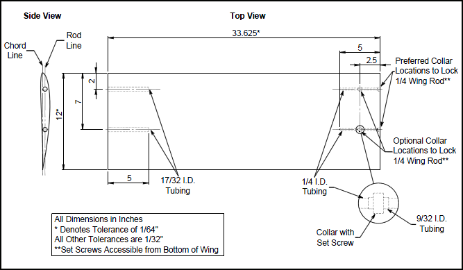
Important Dimensions
- Span = 33 5/8 inch
- Chord = 12 inch
- Distance between tubing centers = 5 inch
- Tolerance = +0, -1/64 inch for span and +/- 1/64 inch chord length
- Tolerance = +/- 1/32 inch for all other dimensions
Materials Supplied
- 1/4 inch I.D. brass tubing for right side of model
- Two 5/16 inch collars with set screws for right side of model
- 17/32 inch I.D. brass tubing for left side of model
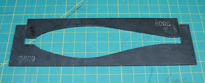
- CNC machined airfoil master template (if requested). Two part sliding template (example):
Wind Tunnel Model Accuracy
The accuracy of the wind tunnel models cannot be over-emphasized. All airfoils are round in the front and sharp in the back; what separates the good from the bad is what happens inbetween. The difference in shape between a "good" airfoil and a "better" airfoil is not large. However, since the difference in drag can be quite significant, it makes it worthwhile to be as accurate as possible. Accuracy is important from a different standpoint as well. Extremely accurate lift and drag measurements will be taken in a wind tunnel with excellent flow quality, and each airfoil will require approximately 16 hours of tunnel time to span a range of Reynolds numbers and angles of attack. If the models are of comparable quality, then the measurements are meaningful; otherwise, they are not. To aid in building the most accurate model possible, you will be sent if requested CNC machined female templates of the airfoil contour.
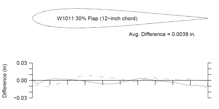
All wind tunnel models are measured using a CMM (coordinate measuring machine) to check their accurate. We post-process the CMM data to make a plot of the model coordinates overlaid with the true airfoil coordinates. The process of making the overlay involves using a least-squares (best) fit between the model airfoil coordinates and true airfoil coordinates. Examples of these kinds of plots are found in our books of airfoil data. Here is an example:
Suggestions for Being Accurate
The most important step involves making the rib templates (or foam core templates). This step should not be rushed. After the model is assembled and ready to be sanded, check the profile with the female templates. Put the female template on the model and shine a light from the other side. If light shines through between the model and the template, the model should be sanded until the template and the model agree. A separate template should be used to check the model leading edge in the same way. If you are aware of inaccuracies with your model, rework the model until it is accurate.
General Notes
- The wing rod line should be located in the same place on both ends of the model. Determine the location of this line by centering the larger 17/32 inch I.D. tubing between the upper and lower airfoil surfaces on the aft end of the airfoil. The wing rod line and chord line, however, should be parallel. If this is not possible, please call.
- Special care should be taken not to deform the brass tubing.
- The brass tubing should be inserted into the model with the uncut ends facing outward. Important: (1) Put the brass tubing in last and glue it in permanently, (2) don't get glue or paint on the inside of the brass tubing (cover the hole with tape if you have more work to do on the model), and (3) as a final check see if you can fit the next smallest size brass tubing into the 1/4 inch and 17/32 inch I.D. tubing. If you drop the tubing supplied, chances are that the ends will get bent and the test above will fail. So buy or ask for new tubing if those supplied are dropped. In case you're wondering, we do fit the 17/32 inch and 1/4 inch O.D. size rods into the model in the lab before installing the model in the wind tunnel. Also, please completely install the collars (glue them in) with the set screw extending completely through the 1/4 inch I.D. tubing. If you follow the steps above, it will eliminate 99% of the problems that we have with wind tunnel models, and we will end up taking more data.
- The 9/32 inch I.D short tubes (sometimes supplied, see collar details in drawing above) should be cut and then slipped over and glued onto the 1/4 inch I.D brass tubing at the location on the collars. The collars should then be slipped over these short tubes, and the set screws extended through holes in both brass tubes so that they can lock onto a 1/4 inch wing rod. On this rod, we have machined a flat for the set screw.
- The set screws must be accessible from the bottom of the airfoil. Large cavities around the collar/set screw should be avoided.
- It is also preferred to have the collars mounted just inside the right end of the model to minimize aerodynamic disturbances. (See figure).
- The surface finish must be smooth.
- Try to avoid bumps that form along glue seams, since they can cause early and unwanted transition to turbulent flow.
- The trailing edges should be as sharp as designed. If this is not possible with the given construction method, XFOIL can be used to modify the coordinates in the trailing edge region for added thickness. Any questions on this subject should be sent to Prof Michael Selig.
- No wing twist should be present.
- The first 70% of the upper surface is the most important part of the airfoil, and therefore it should receive the most attention.
- After that, spend any remaining time on the leading edge region.
- The center of the line on airfoil plots represents the exact coordinates.
- Color: We prefer black models. If the model is going to be covered with Monokote or some other similar covering, we especially prefer black. The black covering allows use to readily do surface oil flow visualization should we want to do that.
- If you have any questions, please call Prof Michael Selig or the LSATs Coordinator.
Special Considerations
- We prefer the models to be as light as possible, but please remember that the forces on the models can be substantial at higher speeds. We have had flutter problems with models that are particularly heavy, so please keep this in mind when selecting materials for manufacture. Be careful not to sacrifice strength and stiffness in order to achieve light weight though.
- Please use a spar. At the higher Reynolds numbers, models without spars become quite bowed, so the potential is there for catastrophic failure!
- In the past, we would sometimes allow the rod spacing to be decreased to 4 1/2 inches. Due to limitations on our set-up, we now prefer it if you could keep the spacing to 5 inches. In some instances this will mean that the rods cannot be aligned with the chord line anymore. If that is the case, please contact us before installing the tubes. We will probably decide to angle the "rod line" (the line connecting the rods).
- If it is at all possible, please use cores made from "SpyderFoam". Some preliminary studies indicate that the results are much more accurate than cores cut from common white, blue, or gray foams. During the process of cutting the foam, its surface is melted first on one side and then on the other as the cutting wire passes around the core. We think this process produces stresses that get locked into the core and cause it to develop a chordwise warp. With SpyderFoam's higher density and different structural properties, it seems to be much less susceptible to this type of distortion.
Shipping of Models
- It is highly recommended that the shipping box be made out of wood. We have never received damage models shipped in wooden containers. We have received many damaged models shipped in cardboard containers. Most of these were returned to the builder for repairs. Tunnel time is pretty special, so we generally don't have time to make fixes while taking data during a tunnel slot. We usually have only two tunnel slots in a given year.
- Cardboard shipping boxes can be found at bicycle shops and moving companies, e.g. U-Haul, etc.
- If you do use a cardboard box, a "light" cardboard box is easiest for shippers to carry and stack. Also, lighter boxes are stacked on top of heavier boxes (e.g. wooden boxes) in U.S. mail or UPS trucks, and stand less chance of getting crushed (vs "heavy" cardboard boxes).
- Write "FRAGILE" on the box.
- The model should be cushioned inside of the box with foam rubber, newspaper, Styrofoam "peanuts," or similar material to absorb major shocks.
- The models should not be securely strapped to the box. Models strapped to the box will be cracked if the box cracks from being dropped or thrown around.
- For best packaging, place airfoil models in foam cores, with packaging material around the foam cores. Do not allow tape to stick to the model, especially if the paint is still drying(!).
- Plenty of tough packaging tape should be placed over the seams of the box and at the corners.
- Models should be mailed to:
Dept. of Aerospace Engineering
University of Illinois at Urbana-Champaign
306 Talbot Laboratory, 104 S. Wright St.
Urbana, IL 61801-2935
USA
(217) 244-5757