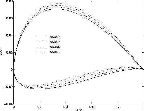
Figure 1 Overlay of the SA7035, SA7036, SD7037 and SA7038 on an expanded scale.
It is clear that of those flying the SD7037 some would like to have the airfoil a little faster, others perhaps slower, some thicker and others thinner. One approach to the problem would be to simply change the thickness and camber of the SD7037 as desired. But by how much should the camber and thickness be changed? And what will happen to the aerodynamics in the process? To avoid these questions, we took a different approach. Using the inverse airfoil design code PROFOIL [Ref 2], we systematically designed the airfoils to share common aerodynamic characteristics from the outset.
We have recently finished the design of the first three in the series - the Selig/Ashok Gopalarathnam SA7035, SA7036, and SA7038 shown in Fig. 1 together with the baseline SD7037. The corresponding velocity distributions are shown in Fig. 2. Each airfoil is 9.2% thick, and for reference the camber values for the SA7035, SA7036, SD7037, and SA7038 are 2.6%, 2.8%, 3.0% and 3.3%, respectively.

Figure 1 Overlay of the SA7035, SA7036, SD7037 and SA7038 on an
expanded scale.
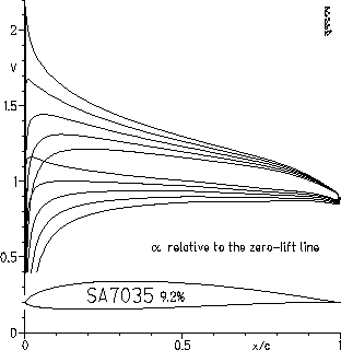
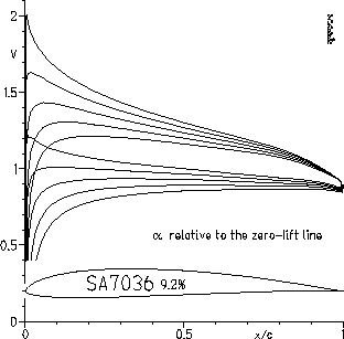
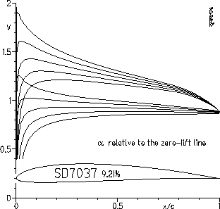
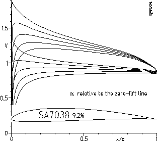
Figure 2 Inviscid velocity distributions for the SA7035,
SA7036, SD7037 and SA7038 airfoils at 2, 4, 6, 8, and
10 deg relative to the zero lift line.
The performance predicted by Mark Drela's XFOIL program [Ref 3] is shown in Fig. 3 for the new airfoils and compared with that of the SD7037. The data is plotted for a reduced Reynolds number of 125,000. When the data is plotted in this way, the airfoil polars can be compared without having to interpolate on the Reynolds number as the sailplane speed changes with lift coefficient. Put simply, the drag coefficient plotted is that experienced by the aircraft in flight over its entire speed range. As seen the first two (SA7035 and SA7036) are lower lift versions of the SD7037 and the third (SA7038) is a higher lift version. For comparison, the SA7035 is shown in Fig. 4 together with the SD7080. As seen, the SA7035 is an improvement over the SD7080 over most of the performance range. In particular, the low-lift/high-speed and high-lift/low-speed ends of the polar are extended at the price of slightly higher drag through the middle range.
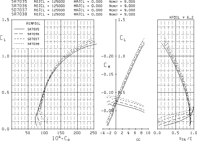
Figure 3 SA7035, SA7036, SD7037 and SA7038 predicted performance for a reduced Reynolds number of 125,000.
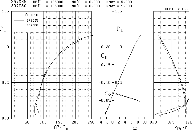
Figure 4 SA7035 and SD7080 predicted performance for a reduced Reynolds number of 125,000.
Our plans are to have some of these new airfoils wind tunnel tested during the current test series, which has started as of this writing (January 97). We are also planning to design two similar series, one 7.7% thick and another 6.2% thick. The final family of airfoils will therefore consist of 12 airfoils, one of which will be the SD7037. When this airfoil family is complete, sailplane designers will be able to make fine adjustments to the performance of a new design. Specifically, from one sailplane design to the next, designers will be able to migrate through the airfoil family until the best airfoil combination (root-to-tip) for a particular configuration/weather conditions is selected.
An airfoil family like this has been needed for quite some time, although now it is especially important since the majority of designs have evolved to using a single airfoil, which is not likely to be the optimum over a range of sailplane sizes and weather conditions. Expect to see more variety at this years Nats! Finally, coordinates and performance data (a mix of experimental and predicted data) for all of the airfoils will be included in the next Summary of Low-Speed Airfoils book. For coordinates, click here
 SA7035
 SA7036
 SA7038
References
Copyright 1997 by Michael S. Selig and Ashok Gopalarathnam
All rights reserved.